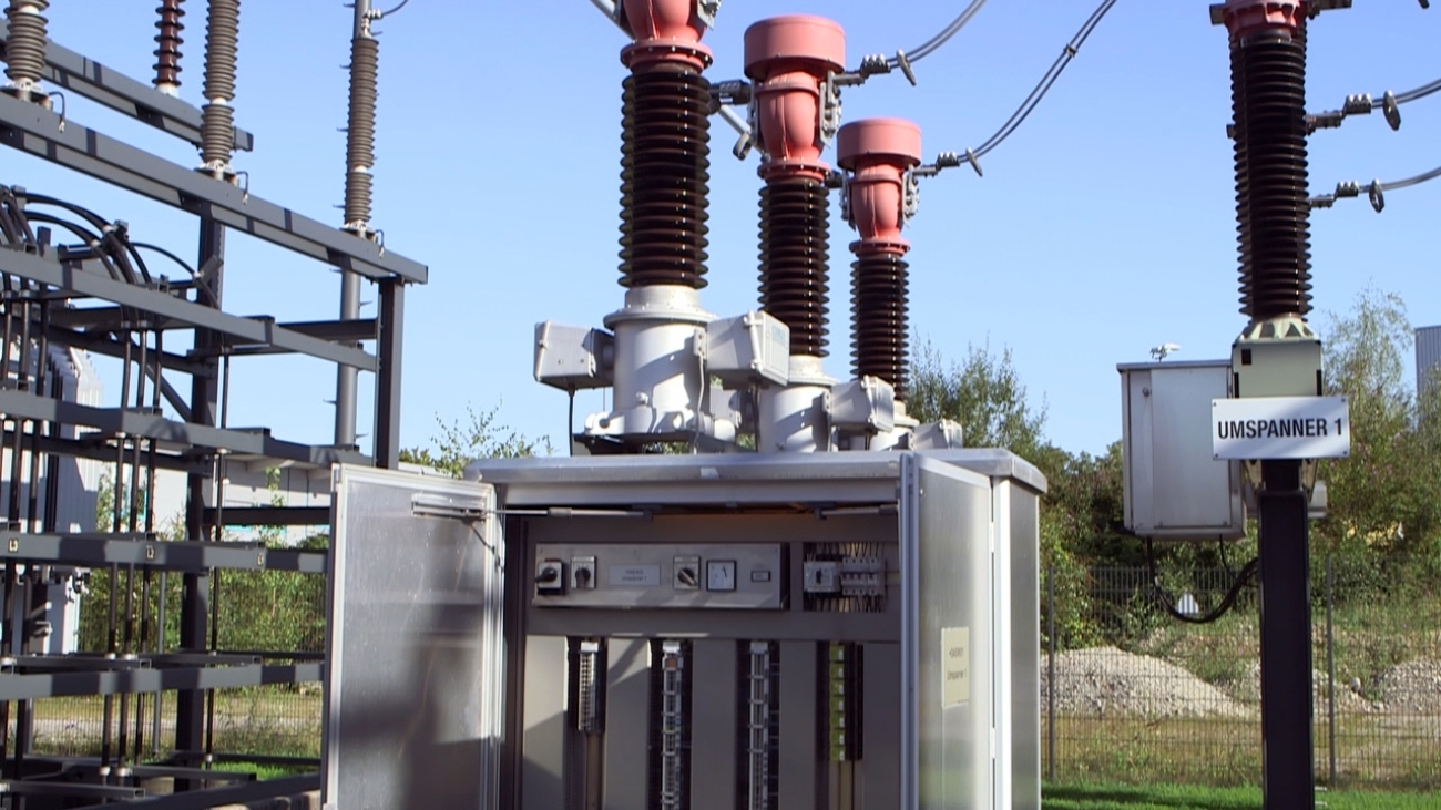
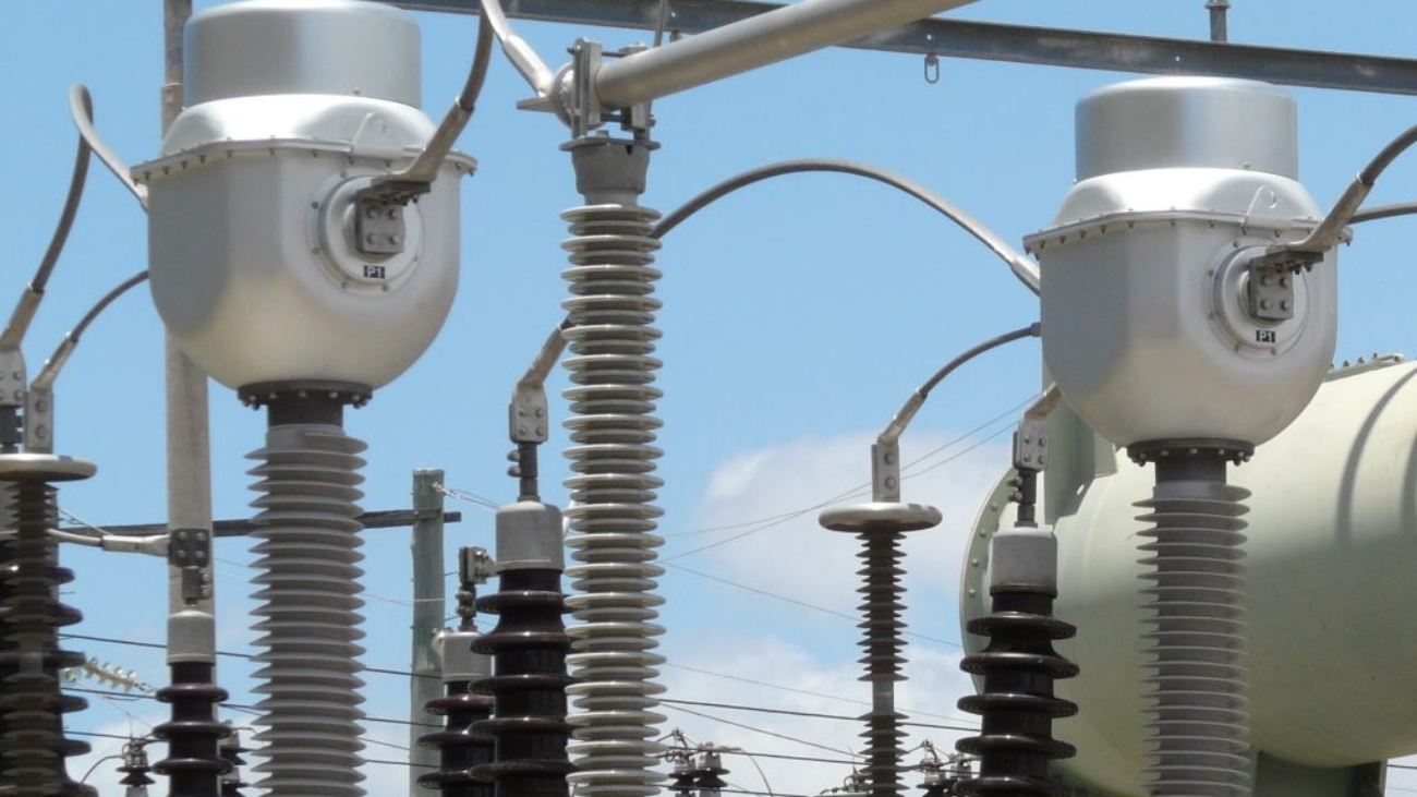
current-tranformer

Current Transformers

This current transformer is an essential part of the power system. The basics of the current transformer including construction, applications, working principles are going to be discussed in this article. Moreover, some practical aspects such as grounding and connections of current transformer and associated errors will be examined comprehensively.


What is Current Transformer & Why is it used?

Current Transformer is an ‘instrumentation’ transformer which steps down high values of currents to lower values.

As evident from their name, Instrumentation transformers are used to isolate the instrumentation devices from high voltages and currents to facilitate the measurement of electrical quantities.

Current Transformers are used extensively for measuring current and monitoring the operation of the power gridThe need for Current Transformer is justified by two reasons:

  1. It isolates the protection system from high voltages and currents, resulting in the reduction of the size and cost of protection equipment.
  2. The output of a Current Transformer is standard (i.e. 1A or 5A) which eliminates the need for protection equipment e.g. relays having diversified operating values.


Construction of CT (Current Transformer):

The construction of a Current Transformer is very similar to a normal transformer. The core of the current transformer is built up with lamination of silicon steel.

A current transformer (CT) basically has a primary coil of one or more turns of heavy cross-sectional area. In some, the bar carrying high current may act as a primary. This is connected in series with the line carrying high current.

The secondary coil of the current transformer is made up of a large number of turns of fine wire having a small cross-sectional area. This is usually rated for 1A or 5A.
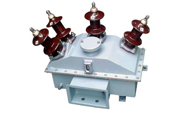
What-is-a-potential-transformer

Potential Transformers

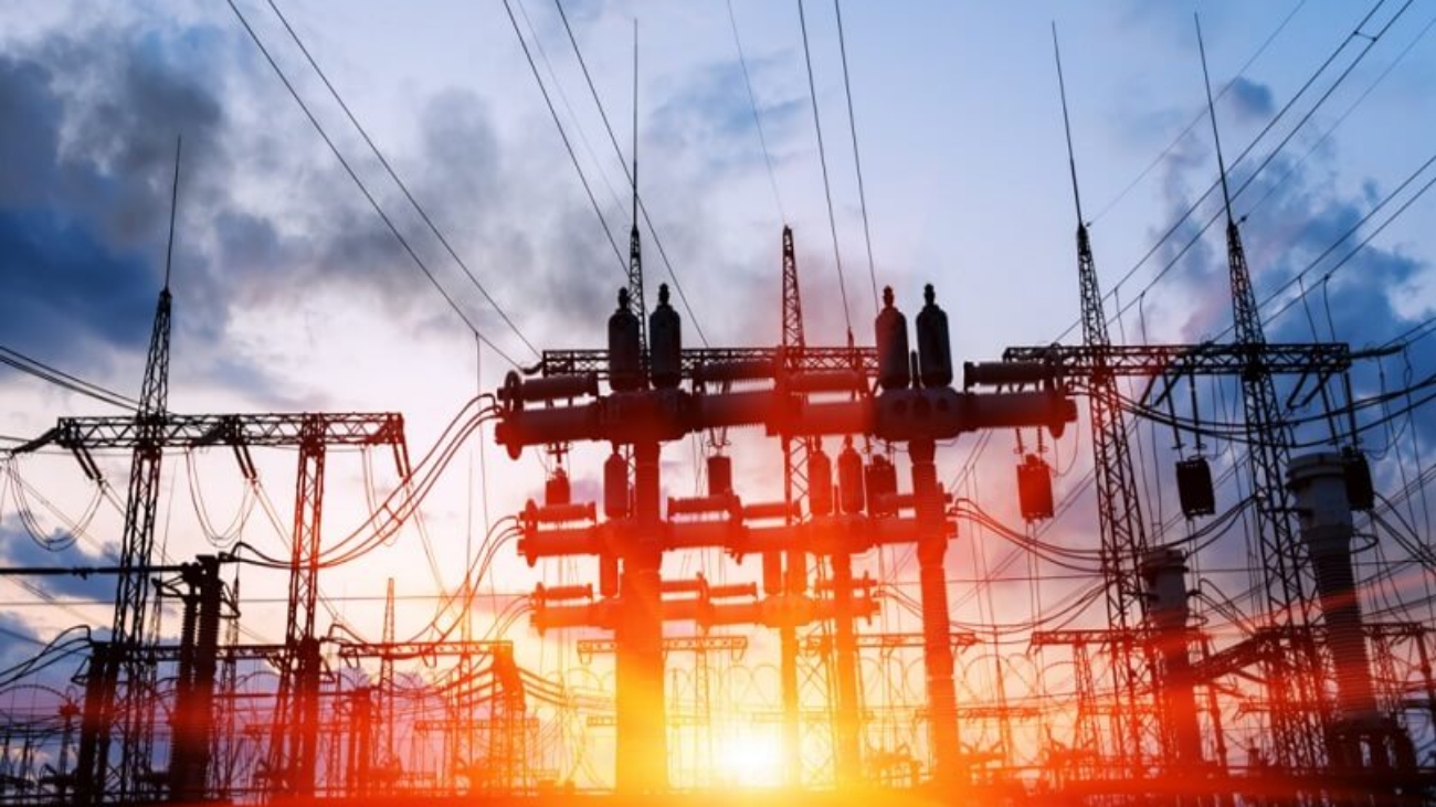
Since the origin of the cardinal constant-potential transformer in 1885, transformers have become indispensable for the transmission, dispensation, and utilization of electric power. Among many types of transformers, potential transformers are high-class accuracy electric devices used for the isolation or transformation of voltage. If you want to learn more about the working principle of potential transformers, this article will help you.


What is a potential transformer?

The potential transformer is a device that reduces high voltages to a much lower and usable voltage level where it can be used to supply electrical equipment or measurement devices. It is also called a voltage transformer.

A potential transformer has three key functions:

  • It adapts the value of the voltage on the primary to the characteristics of metering or protection devices by supplying a secondary voltage that is proportional and lower.
  • It isolates power circuits from the metering and/or protection circuit.
  • It senses abnormalities in voltage and gives voltage signals to protective relays to isolate the defective system.


How does a potential transformer work?

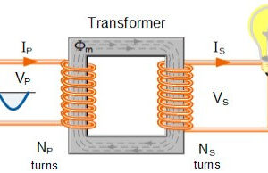
The potential transformer is capable of decreasing the voltage levels of its supply, without modifying its frequency. The voltage being measured connect the primary winding which has a large number of turns and is connected across the circuit. The secondary winding, which has a much smaller number of turns, is coupled magnetically through the magnetic circuit to the primary winding.


The potential transformer reduces the voltage to a reasonable operating value. Primary winding consists of large numbers of turns while the secondary has less number of turns. The primary is connected across the high voltage line while the secondary is connected to the low range measurement device coil. The potential transformer is always a step-down transformer.

Potential transformer ratio

The difference in voltage between the primary and the secondary windings is achieved by changing the number of turns in the primary winding compared to the number of turns on the secondary winding. As the transformer is a linear device, a ratio now exists between the number of turns of the primary coil divided by the number of turns of the secondary coil. This ratio is called the ratio of transformation, more commonly known as a transformer “turns ratio”. This turns ratio value dictates the operation of the transformer and the corresponding voltage available on the secondary winding.

It is necessary to know the ratio of the number of turns of wire on the primary winding compared to the secondary winding. The turns ratio, which has no units, compares the two windings in order and is written with a colon, such as 3:1 (3-to-1). This means that if there are 3 volts on the primary winding there will be 1 volt on the secondary winding.

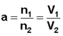
The formula of the potential transformer turns ratio:

a – Turns ratio

V1 – Primary Voltage

V2 – Secondary Voltage

N1 – Number of Primary Windings

N2 – Number of Secondary Windings

1

Voltage Transformer

What is a Voltage Transformer Used For?

Voltage transformers are devices that are used to step down and decrease the voltage of a system to a level that is considered safe. It operates by allowing energy meters to monitor the operation of electrical connections, which may have a higher voltage than usual to function correctly.

Depending on the application, it can be used as a low voltage transformer or as a high voltage transformer. Specifically, voltage transformer can be used as:

  • A useful instrument to measure the consumed energy.
  • A device to secure and prevent disturbances and faults from happening in the electrical systems.
  • Voltage signals are used crucially for synchronizing, event logging, and recording events.
  • A computer of the impedance and power of a system in the process of voltage measurement along the direction.
  • A determiner of O/F, O/V, U/F, U/V, and some excessively fluxing security through the measurement processes.